after passing through buffers and inverters. The CLK and CLK BAR in Figure 6 that controls the switching of the transmission gates, come after the ramping up of the CLK signal, i.e. In Figure 6, input data D is given to the inverter, or any other logic sitting before transmission gate T1, and is a part of the flip-flop.

The darkened line shows the conducting path for hold time.Īs previously indicated, HOLD time is measured with respect to the active CLK edge only. Note that setup and hold time is measured with respect to the active clock edge only.įigure 6. Violation in this case may cause incorrect data to be latched, which is known as a hold violation. Hold time is defined as the minimum amount of time after the clock’s active edge during which data must be stable. Any violation may cause incorrect data to be captured, which is known as setup violation. Setup time is defined as the minimum amount of time before the clock’s active edge that the data must be stable for it to be latched correctly. It is here that we introduce SETUP and HOLD time.

In summary, if D changes, the change would reflect only at node Z when CLK is LOW and it would appear at the output only when the CLK is HIGH. Any change in input is reflected at node Z which is reflected in the output at the next positive edge of CLK.

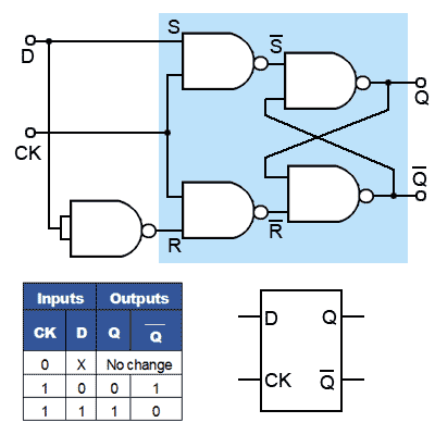
When the CLK is LOW, the RHS latching circuit is enabled (See 4c) and there is no change in output. Hence it is a positive edge triggered flip-flop. Note that the output arrives at the positive edge of CLK. It latches 1, which results in Q = 0 (which is what it should be for D = 0). When the CLK is HIGH (See 4b), latching circuit on LHS is enabled. The workings of a D flip-flop whereby the darkened line shows the conducting path.


 0 kommentar(er)
